Creating Chamfered Cuts on Corners
Creating Chamfered Cuts on Corners
Today I’m going to be showing how to model what I called a chamfered cut, meaning a chamferd section of an edge, often found on hard-surface metal parts.
So without further introduction, let’s get to it.
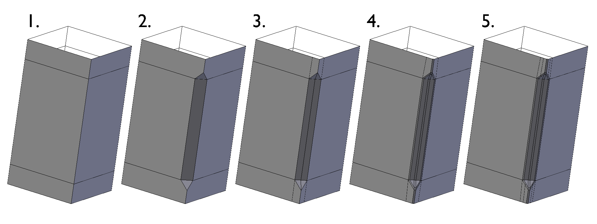
1.
Start off with adding two edge loops to define the area that you want to chamfer.
2.
Next, bevel the edge created by adding the two edge loops to create the basic chamfered shape.
3.
Connect the two points of the triangles near the corners of the shape to make an edge loop down the center of the chamfered area. Also, connect the other two points of the triangles down to remove the n-gons from the model.
4.
Bevel the outer corners of the chamfered area a small amount to make sure the edges are held if subdivisions are applied.
5.
Add more holding edges to the outside to keep the shape contained, then add sub-surf if desired.
That’s it!