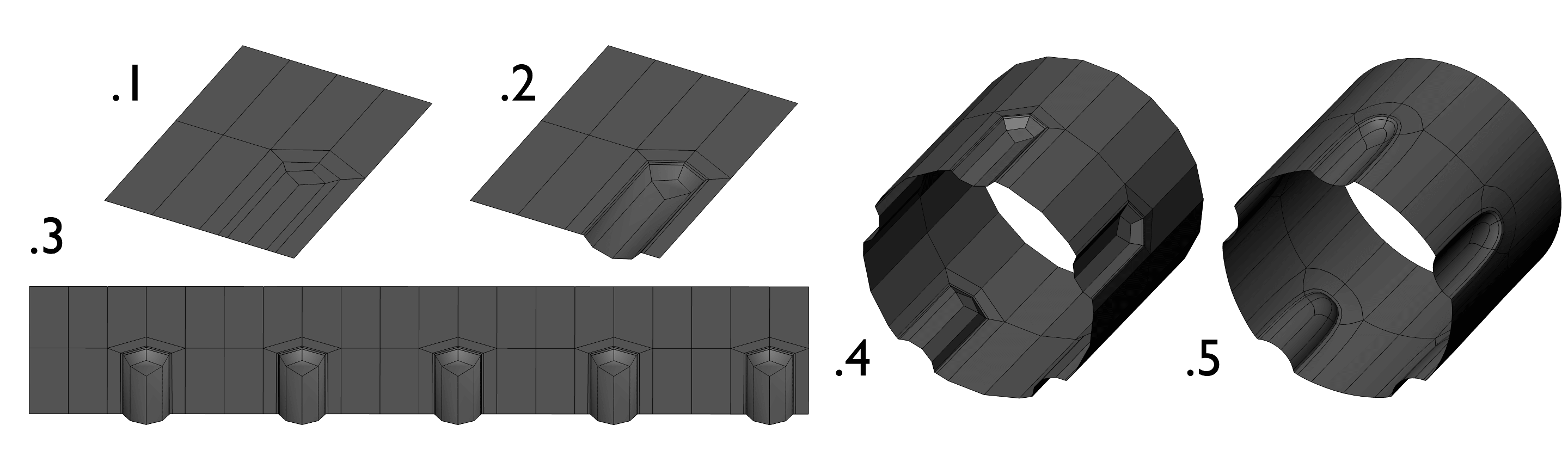
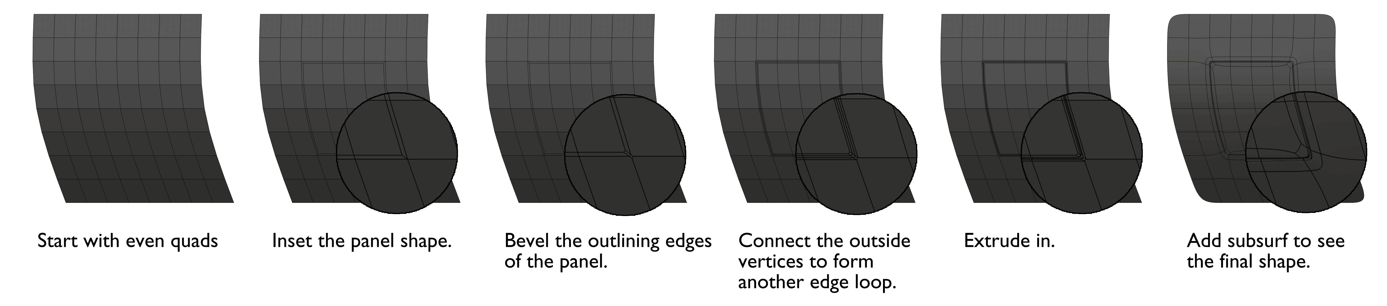
This shape is pretty simple. but a useful one if your modeling mechanical or sci-fi things with grips or ridges. So let’s get to it!
1.
Start by modeling the curved edge you need to incorporate the ridges into. I recommend modeling separate to your main model so that you can tile it later and then add it back in.
2.
Add two loops to define the inset and outset parts. If you want the inset and outset ridges to be the same width, then make sure the middle section is the same width as the two outer sections combined.
3.
Cut out the area you’d like to be inset.
4.
Add a quad to the first four vertices along what will be the wall of the inset. Make sure to model this quad to be properly aligned how you
like it, as the rest of the inset will be based upon this quad.
5.
Fill in the rest of the inset using the fill tool (F key), or using the F2 add-on for Blender to make it even quicker.
6.
Add holding edges or mean creases to hold the shape, then apply sub-surf. At this point, you can easily tile the ridges using an array and reintegrate it into your mesh.
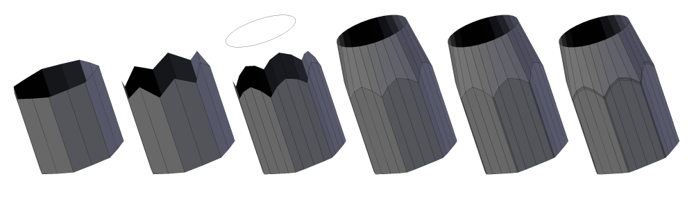
I’m back! At least for now. Today i’m answering a question about cutting circular holes in curved surfaces. I learned this technique from the great Chris Kuhn a few years ago and have used it ever since.
1.
Start with even quads and an even mesh density.
2.
Add a Circle with an amount of sides relative to the density of the surface.
3.
Add a Shrinkwrap modifier to the circle, and set to project onto the surface area. (Be sure to set the direction and axis of projection.)
4.
Cut necessary areas in surface and merge vertexes along the edge of the hole with the circle. (Be sure to merge to the circle to maintain the circular shape.)
5.
Finish by checking geometry for errors or improper curvature.
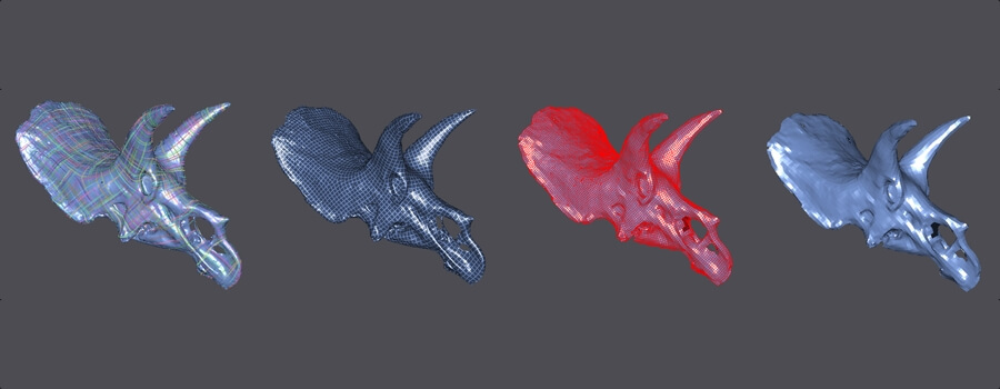
I recently had the honor of writing a tutorial for the Sketchfab Blog about retopologizing 3d scans. I thought this would relevant to this blog so I’ll share it with you.
Retopology is the process of rebuilding your model to reduce polygon count and to allow for UV unwrapping and proper deformation for animation models. Retopology is widely used by digital sculptors to convert their models into usable assets in game or film projects. It can also be used on 3d scans for rapid asset creation. Learning the process is quickly becoming a valuable task as more and more game studios are using 3d scans in their asset pipeline.
Instant Meshes for Retopology
For the retopology we’re going to use Instant Meshes, a free quad-based auto-retopology software recently announced at Siggraph and available for free download. At the moment Instant Meshes supports OBJ, PLY, and ALN formats. By coincidence, the model I’m using is already in OBJ format. But if your model isn’t, there are a number of free converters such as MeshLab or online apps if you prefer not to download one.
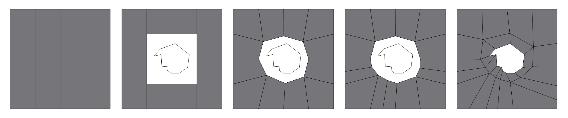
Recently, I received a question in regards to cutting a custom hole onto a surface. Instead of addressing a unique situation, I thought I would give some guidelines for cutting holes. So here it goes.
The Shape
Start by modeling the shape you would like to cut, make it as minimal in vertices as possible. Then place it onto the area you would like to cut it onto.
Basic Form
Delete the major areas needed to make the hole. Again, be minimal in what you delete, only what is necessary.
Shaping the Hole
Shape the vertices to fit around the shape. Don’t move them in too close, make sure there will be room for an edge loop with faces that are consistent in size with the rest of the mesh.
Counting the Loops
Count the vertices around the hole and the shape. Most likely they are uneven. If so, add and remove loops from both the shape and the rest of the mesh. This will be difficult, it may require you to retopologize parts of the mesh in order to make match.
Filling the Gap
Start filling the faces in. Rearrange the varices to make sure the faces are even is size as much as possible.
Mesh Check
After you’re done, check over the model to make sure you didn’t mess up other parts of the model while deleting or adding edge loops. Especially if you’re doing sub-d modeling.
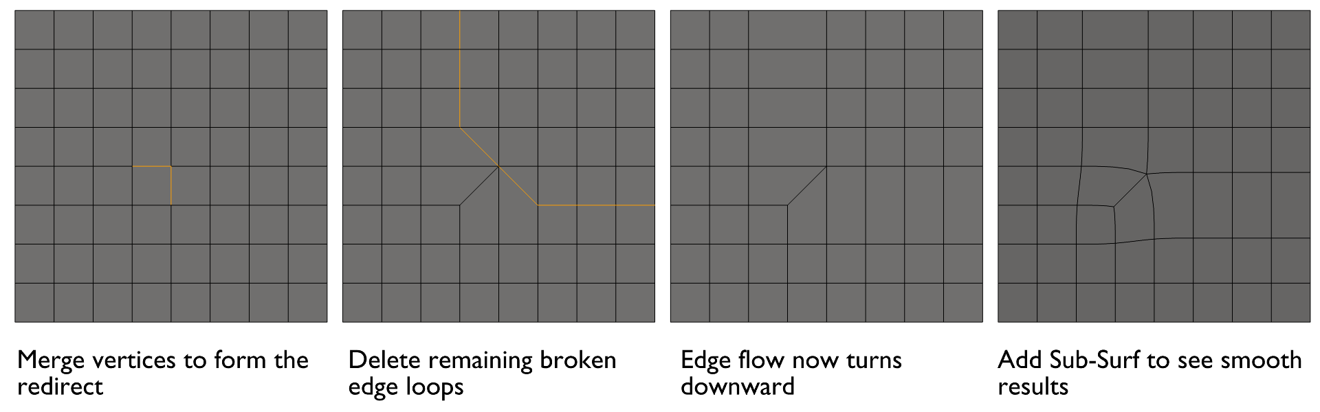
Here’s a few tips to keep in mind when Sub-d modeling. I hope you like this written format. If not, let me know.
1. Always start with an accurate Blocking
Blocking is one of the most important stages of modeling. It’s where you define the scale, style, and look of your model. That’s why you should always start with an accurate base shape. Because once you start adding lots of details and holding edges it’s hard to change a shape without getting a big headache.
2. Use as few Polygons as possible
When sub-d modeling you don’t need to worry about keeping curved surfaces smooth because once you apply a few levels of sub-surf (subdivision surface) you won’t be able to see how “low poly” your model really is. Why should you use a 32 sided cylinder if you can use a 6 sided one and apply some non-destructive sub-surf instead? So keep your models as simple as possible. If a polygon doesn’t perform a specific task, then most likely it should be deleted.
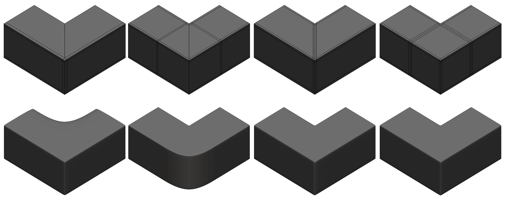
3. Tris and N-gons aren’t always Bad
Tris and n-gons have a pretty hideous reputation of ruining topology, but if used in the right circumstances, they can be useful. And in the end, they will be turned into quads anyways. Don’t take this as a green light to use non-quads all you want, but don’t freak out if you have one or two that aren’t ruining your topology flows.
4. Keep your Quads Square
I know you’ve probably heard this one a zillion times. But I still see lots of models with very rectangular quads. This is one of the most basic things you can do to your model to improve it. Keeping your quads square will help keep your model looking even and smooth. As well as helping other tasks like UV mapping.
5. Model using Modifiers
Modifiers are non-destructive. Meaning you can turn their effects on or off at any point in your modeling process. Different 3d modeling apps have different tools. But whichever app you’re using, find out which modifiers could help you when modeling. They can save hours of work.
6. Creases for small or distant Objects
Instead of adding holding edges to keep your corners sharp, crease your edge instead. It will keep your polygon count down and will look perfectly adequate for small or distant objects.
 See the final result on Sketchfab: